Power
On the mixer side, we used a transformerless power supply to power the microcontroller. Transformerless AC power supplies accept wall-outlet AC voltages (here ~120VAC ) input and produce a low voltage DC output (such as 5 volt here for the micro controller). As for the remote control side, the microcontroller was powered using a 9V alkaline rechargeable battery. We used analog-to-digital conversion to check on the battery level and alert the user via a LED when the voltage drops below a certain threshold value.
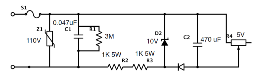
Power Supply Schematic